

The Importance of Heat Recovery
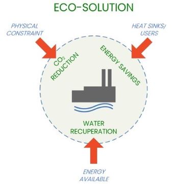
A significant amount of waste heat is generated as a by-product of the papermaking process. Most of this heat cannot be reused directly in the process as it has a high level of humidity and/or contains unwanted gaseous or particulate contamination. Heat recovery equipment (Figure 1) is a key element of energy-efficient mill operations, providing:
- Competitiveness/energy savings
- Greenhouse emissions reduction
- Reduced boiler load
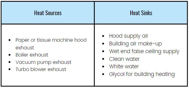
Planning a potential heat recovery project for greenfield or rebuild projects requires a quantitative analysis of the potential heat sources and heat sinks.
Planning Economically-Viable Heat Recovery Projects
Return on investment (ROI) is a key factor when comparing various potential heat recovery projects and for final approval, ROI depends on:
- Total project cost: in general, using a source having a higher heat capacity results in smaller, less expensive heat recovery equipment
- Calculated annual energy savings: only recovered heat that is useful shall factor into this calculation (i.e. heat recovery for building ventilation is normally not required during the warmer months)
Turbo Exhauster as a Heat Source
Turbo exhausters are an alternative to conventional liquid ring vacuum pump systems for dewatering and felt conditioning in paperboard manufacturing. The high speed of the motor and compression of the air generate a tremendous amount of heat, which is sent to the exhaust stack. In Europe and Asia, over 90% of turbo exhauster installations include air-to-air heat recovery systems. Heat recovery can be installed together with the turbo exhauster or subsequently as a retrofit project. In North America, however, less than 10% of turbo exhaust systems have heat recovery. Turbo exhaust air contains a tremendous amount of sensible heat and approximately 70 to 75% of it can be recovered and used for a variety of useful applications.
Air-to-Air Heat Recovery
Un échangeur de chaleur indirecte à tubes a été conçu pour répondre aux besoins de chauffage du système de ventilation de poches (Figure 3). L’air de ventilation de poches a été sélectionné comme puits, puisqu’il exige un apport continu en chaleur tout au long de l’année et qu’il est relativement près du turbo exhausteur.
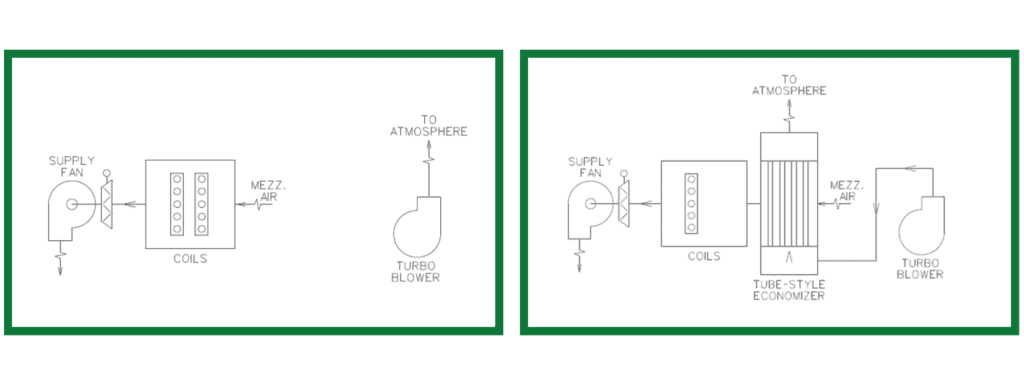
A tube-style design was selected (Figure 4) as it provides great flexibility in terms of overall dimensions. This is key for rebuild projects as available space for new equipment can be quite limited. Stainless steel tubes were sized and arranged in order to meet the following key requirements for the project:
- Pressure drops across and through tubes so that no additional booster fan would be required
- Velocity through tubes sufficiently high so as to have turbulent flow and hence a maximized heat transfer coefficient
- Velocity slow enough to allow air sufficient time to collect heat
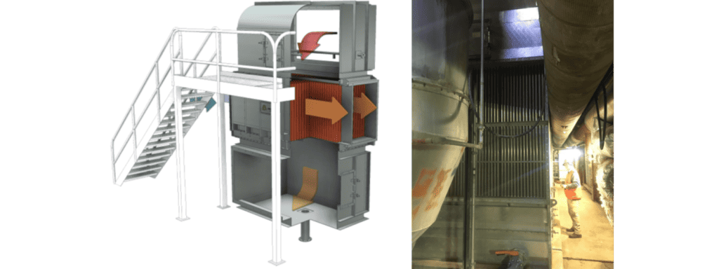
A plenum was provided above the tubes to house showers that clean the tubes. Water for this cleaning process as well as any condensation that is generated will be collected by a stainless steel sump which also acts as a support for the equipment. Installation was mostly completed while the machine was on-the-run. A short machine maintenance outage was required to tie ductwork into the existing system.
Results
The heat recovered from the heat exchanger was sufficient (Table 1) to raise the temperature of the supply air for PV4 system from ambient to target without use of steam coils. A total of 3.80 MMBTUH of heat is being recovered by the system, which slightly exceeded the theoretical projections prior to start of project. The return on investment of the project (installed) was less than 18 months. The air temperature of the waste heat exiting the economizer was found to still be very high (211 Dry Bulb/134 Wet Bulb). This helps to illustrate just how much heat is available in the exhaust stream and that further heat recovery downstream is still possible.
| Air Flow(CFM) | Air Temp. IN [°F] | Air Temp. OUT [°F] | Heat Recovery [MMBTUH] | |
| Exhaust Side (from Turbo) | 47 500 | 317/140.4 | 211/134 | 3.80 |
| Supply Side (to PV4) | 49 300 | 111/87.9 | 199 | 3.80 |
Our experts can analyze your machine to identify and quantify potential energy savings solutions. Project payback can be accurately estimated at the early project feasibility stage.
Dave Young, Operations Manager Enerquin USA